


The last few days I had little time and waited for wooden boards and an AMBU Bag that I had ordered online. Unfortunately I did not receive the delivery for 14 days. Because of the exit restrictions and the closed shops it is not so easy to get material. In addition, the German shops do not control the online trade. So there are problems with the integration of the payment via e.g. PayPal in the web-shop if you don’t order at Amazon, but surely also a complete overload of the still active merchants in the net.
Anyway, I was able to build my test setup from still existing material even though it didn’t turn out very nice. But the basic principle works and I can concentrate more on the electronics and sensor technology which I enjoy more anyway.
The following picture shows my current setup.
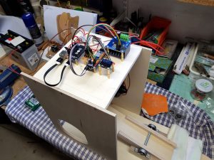
DIY ventilator construction wiper motor test setup
Explanation of the electronics
Since I have already received questions about what exactly I installed on the ventilator on Elektornik, here is a short explanation.Step Down
- Step Down-Converter: With the Step Down Converter a 5V voltage with 3A is generated from the 12V input voltage of the car battery. The Step Down-Converter has two USB outputs. The ESP8266 NodeMCU is connected to one of them and a smartphone, for example, can be charged at the second USB output.
- ESP8266 NodeMCU: The board is used to implement the control of the ventilator. The ESP8266 NodeMCU can be easily programmed with the widely used Arduino IDE. There are also many manuals available on the net. For example, additional sensors can be connected to its I2C bus.
- Voltmeter with display: The voltmeter I have installed to see if the applied voltage is still 12V.
- DIY I2C Hub: The self-built I2C Hub allows me to connect several devices to the ESP8266 NodeMCU. The hub itself is very simple. An explanation of how to build such a hub can be found on my blog here (Build your own I²C Hub).
- 12V Motor Switch: With this switch you can cut off the 12V voltage that is applied to the engine. So I can program and test in peace without the wiper motor turning.
- PCA9685 Servo Controller: With the servo controller, the PWM signal is generated once to control the speed of the motor and a HIGH / LOW signal to set the direction of rotation of the motor.
- Motor Driver: The motor driver is controlled by the servo controller and supplies the motor with a 12V voltage and the necessary current to allow the wiper motor to rotate powerfully.
- OLED Display: The OLED display shows information such as the current PWM signal and the direction of rotation. But of course interesting information can be displayed during the course of the project.

DIY ventilator construction wiper motor details
Video
The video shows my current structure and how it works. Because I don’t have an AMBU Bag yet, I added a small spring, which brings the rocker back when the motor has pressed it down. I will probably attach a Leva Cam to the motor to be able to reproduce the pressure curves mechanically. Here I used the documents of the project https://github.com/ProtofyTeam bedient.

Summary
When I finally receive the ordered AMBU Bag I can continue to take care of the sensor technology. Now I will install them as far as I think it is necessary and write the hull programs for them. I enjoy the project a lot and I learn a lot about the breathing of a person that I never knew before.


Recent Comments