In the last days of March 2020 I looked at a variety of projects and ideas how a self-constructed workaround bridge ventilator could look like and work. I was very much interested in those projects that use almost no 3D printing, use widely available components and are robust in construction. Since I am active in the field of robot vehicles and have experience with the electronics and the control of DC motors or stepper motors, I was able to add my experience to the following list of components.
First I made a drawing of my idea of the construction and drew the sensors and the necessary electronics. Some components like the knobs and the OLED display are still missing in the drawing. Following is my first idea how I would design such a workaround bridge ventilator . It is slightly based on the idea of the Spanish team. Unfortunately there are no drawings or more detailed descriptions from this spanish team.
All components I list now I have either ordered new or have already gained experience with them in my robot projects.
List of components
This is my personal component list of the components I currently plan to install.
Hint: Most links will point to the Amazon web shop. These are affiliate links.
Controller unit
I really like the ESP8266 NodeMCU and the tiny MCU should do the job for less then 3,-$. It is much faster than the Raspberry Pi by processing sensor data and with the build in I²C bus it possible to connect different sensors or for example a servo-controller. The ESP8266 NodeMCU has a build in WIFI module. This enables the ventilator to be controlled over the WIFI by a small web-gui.
12V Wiper motor
Not sure about those wiper motors but they should be available around the world for a few bugs. If the supply chain is not working at all wiper motors should be available in old cars as well. It is the first time I will use them but they look like normal geared DC motors for me.
Update 20200401: I orded those two wiper motors and they work very well.
I orded two wiper motors for around 20,-€ to get a better feeling and understanding for them.
Ball Bearings
For the mechanical part and to move the push lever up and down smoothly I will use those roller ball bearings.
Motor Driver
To drive and control those wiper motors a power full motor driver is need. I already used those motor drivers in different robot projects with 12V and 3A geared DC motors. One of those motor drivers is able to control one DC motor or with two of those motor drivers one 4-phase stepper motor. I am not yet sure if a DC motor or a stepper motor is the best choice. I will test my first setup with a wiper motor.
Additional components
Those components are needed to round up the project. They typically lay around in my robot workshop.
Sensor modules
MPU 6050 6 axes gyroscope and acceleration sensor is used to control the movement of the mechanical push lever of the ventilator. With the sensor I am able to control the speed of the movement, the range of movement and if it is moving at all.
The BME680 temperature-humidity pressure sensor will be used to measure the pressure in the air system / AMBU BAG. Maybe I need two of those sensors to meassure the air pressure outside the AMBU bag as well.
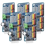
The PCA9685 servo-controller is used to generate the PWM Signal for the motor driver to control the speed of the wiper motor.
The step down-converter is perfect to get out of a 12V power supply 5V for the ESP8266 NodeMCU or Raspberry Pi
The OLED Display is optional and may be used to display some detailed information.
Wires
A bunch of wires I typically use in my robots to connect sensors and all the controllers together.




![Anker Powerline Micro USB Kabel [4-Pack] 0.3m Ladekabel, Einer Lebensdauer von 10,000+ Biegungen für Samsung, Nexus, LG, Motorola, Android Smartphones und weitere (Schwarz) Anker Powerline Micro USB Kabel [4-Pack] 0.3m Ladekabel, Einer Lebensdauer von 10,000+ Biegungen für Samsung, Nexus, LG, Motorola, Android Smartphones und weitere (Schwarz)](https://www.blogyourearth.com/wp-content/uploads/2020/03/41dDOaTwUbL._SL160_.jpg)





Recent Comments